PC will not POST with a DRAM LED: check memory on an ASUS motherboard
What to do first
A persistent DRAM light calls for a controlled memory check. Identify the indicator, disconnect power before handling parts, and compare one module at a time before replacing hardware.
This is a general troubleshooting guide, not an announcement of a current outage.
Affected products and symptoms
- Product
- ASUS Motherboard
- Versions and conditions
- ASUS desktop motherboards with Q-LED; a steady DRAM indicator and no BIOS screen after assembly or a memory change
Symptoms
- Power turns on, but the display stays blank and the DRAM LED remains lit
- Startup checks stop after installing or replacing memory
Causes and conditions
Seating or memory configuration may be involved. The DRAM indicator alone does not identify whether a module, slot or CPU-side connection is responsible.
Before you start
- Have the exact motherboard manual and memory part numbers available
- Prepare an ESD-safe workspace and photograph the current slot arrangement
Precautions
- Never insert or remove memory while powered
- Do not start socket cleaning, CPU removal or a CMOS reset solely because of this indicator
Tools and official pages used in this guide
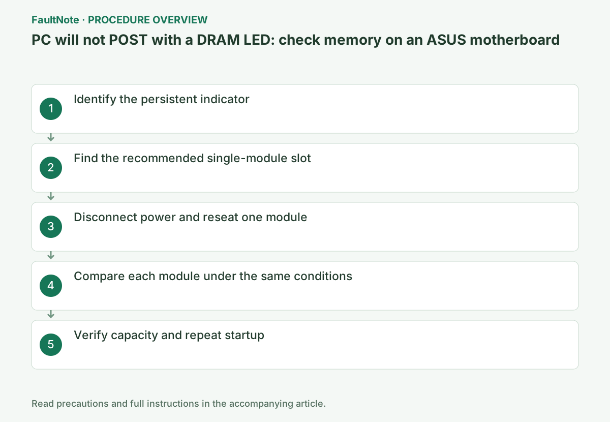
Step-by-step instructions
Read the board labels or manual to distinguish DRAM, CPU, VGA and BOOT. Record the label rather than relying only on its color.
After a DDR5 change, allow the manufacturer-specified memory-training interval. Avoid repeated rapid power cycles while that process may still be running.
Official links for this step
Use the memory-population diagram to identify the slot recommended for one module. Photograph its label so you can repeat the same comparison.
In model support, open CPU / Memory Support > Memory and check the complete part number and supported population. Older pages provide a QVL under Memory / Device Support.
Official links for this step
Turn the PC off, switch off the PSU and unplug its AC cable. Follow the manual preparation procedure and use ESD precautions before opening the case.
Hold the module by its board edges and align the notch in the recommended slot. Follow the actual latch design; do not force a fixed latch or press on chips and contacts.
Official links for this step
Close the case and reconnect power to check for a BIOS screen. Before swapping another module into the same slot, turn off and disconnect AC again.
Record the module, slot, persistent indicator and whether BIOS opened. Change one factor at a time so the comparison remains useful.
If one module reaches BIOS, check its detected capacity. Add matched-kit modules only with power disconnected and in the positions shown by the manual.
Confirm the intended capacity and repeat a restart. Report a pattern such as working individually but failing together instead of concluding that every module is defective.
Check the result
- BIOS opens and reports the installed capacity
- Restart proceeds past the DRAM check and the comparison is documented
If the problem continues
- If every module fails under the same conditions, request diagnosis covering the CPU, socket and board
- If BIOS is accessible and instability occurs only with XMP or EXPO, investigate the profile separately
Scope of this guide
Troubleshooting guide — Separate connection, compatibility and configuration causes using observed results, then verify detection and operation after restarting.
Frequently asked questions
Does the DRAM light prove the RAM is faulty?
No. Seating, supported configuration and a controlled single-module comparison provide more useful evidence.
Is A2 always the correct single-module slot?
Follow the exact board manual; do not assume a universal slot layout or population rule.
Official sources and dates
- ASUS motherboard troubleshooting via Q-LED indicators ↗
- How to query CPU and memory QVL lists ↗
- How to install memory in a desktop PC ↗
- Desktop and notebook memory support ↗
Source publication or resolution date: 2026-04-07. Sources checked: 2026-09-12. The check date is not the date the problem first occurred. Interface labels can vary between versions and display languages.
Related troubleshooting guides
Windows errors and troubleshooting →
- Use Startup Repair When Windows Will Not Start
- Hyper-V is missing from Windows Features or cannot be enabled
- PC will not boot after a CPU swap: check ASUS CPU support and required BIOS
- Desktop Background Turns Solid Black After KB5120998